PC ProPad 4 Arduino Code and Connections

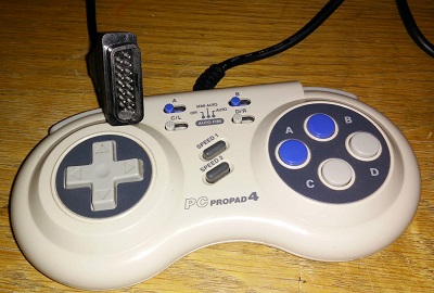
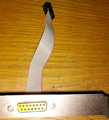
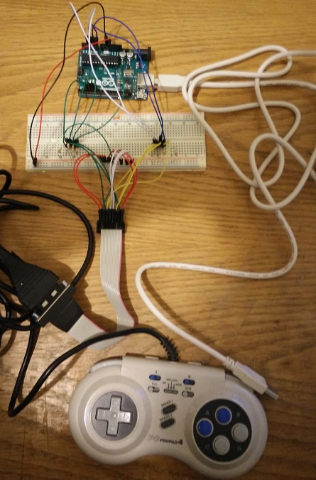
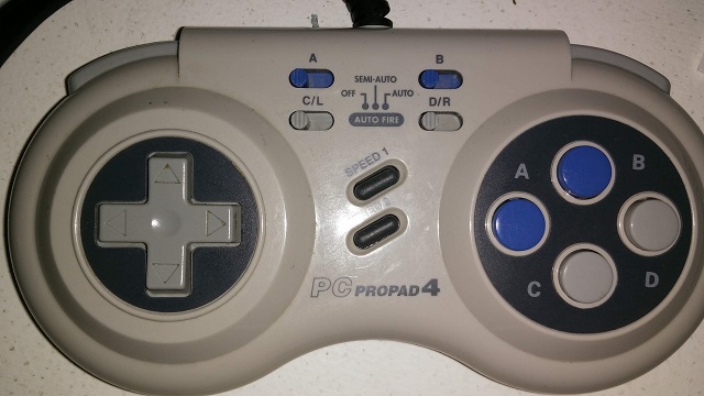
This is a followup to my previous post about the PC ProPad 4. I finally got a chance to figure out the full functionality. I wired it up only using the active connections and created a simple sketch to get more specific output from the connections.  I tried to design it so it would work for any GamePort connection.

PC ProPad4 wiring
PC ProPad4 Wiring.
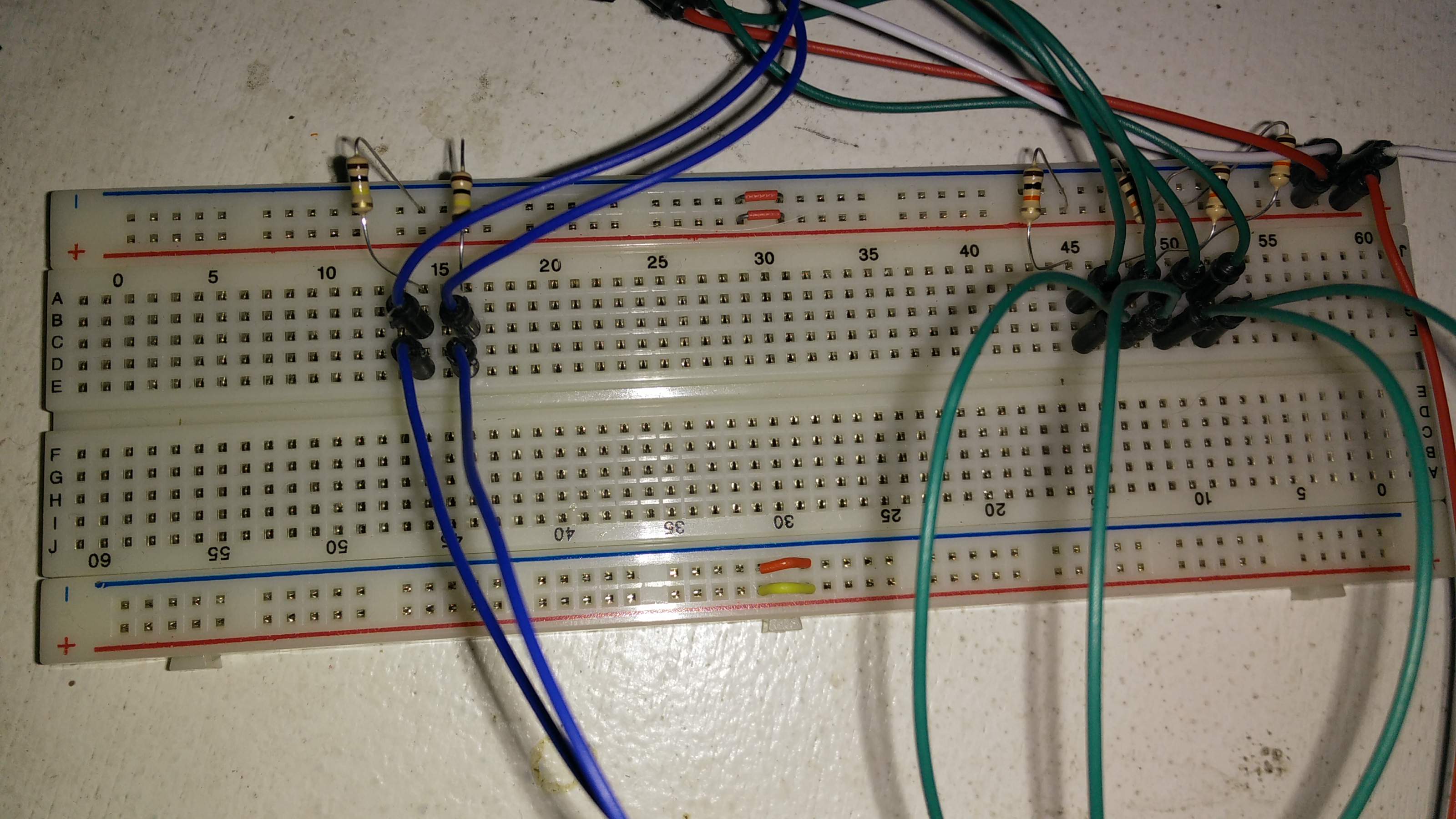
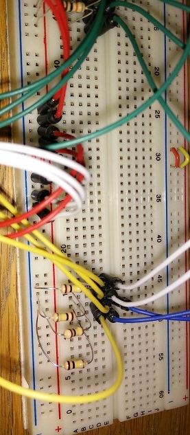
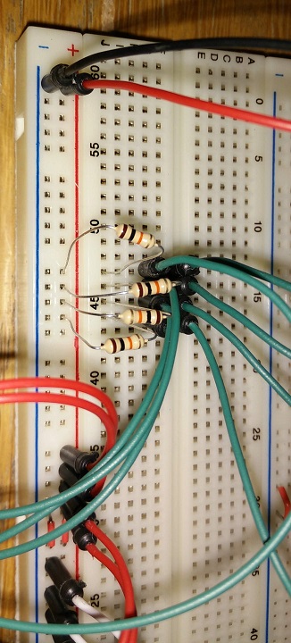
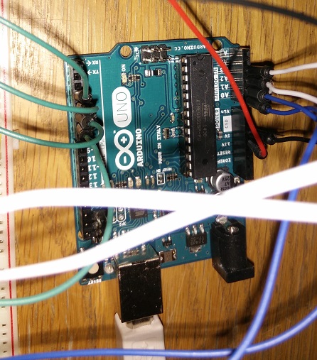
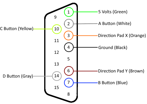
Blue is wired from the X & Y to the analog pins
Green is wired from the buttons to the digital pins
Red is 5v
White is ground

Next a wrote a much more complex sketch specifically for the PC ProPad 4. It allows me to configure interrupts, buttons, speeds, etc. I also wrote it with the intention of controlling a mouse. The Uno only has two interrupts and can’t connect as a mouse, so that part is untested. This sketch and the PC ProPad 4 should ideally be hooked up to a Leonardo or Due. This will allow you to use interrupts for all the buttons and connect it as a keyboard/mouse to the computer.

I will try it on the Netduino, which I believe supports interrupts on all the pins. It seems sending 3v should be fine, I just have to make sure I actually change it to the 3v line so keep the Netduino safe.

The first question I had what was the semi-auto, auto and speed buttons do? When a button is set to semi-auto then holding down the button will continue to fire the bottom (change from high to low). When the button is set to auto, it will fire the button constantly without it being pressed. Once I figured that out I remembered all the Doom 2 games I played with direct modem connections and setting my fire button to auto and having lots of fun.

The second question was what do the speed buttons do? I thought the speed button was some how associated with the analog direction pad, but this is not the case. The two speed settings set how fast the button is pressed when using auto and semi-auto settings. On Speed 1 the button is pressed about every ~30ms. On speed 2 it is pressed as fast as it can. The buttons need to be debounced and you can’t tell the difference between a bounce and the button firing automatically on speed 2, so it really just runs as fast as you are willing to debounce the button.

The next step is to see how this runs on the Netduino, then I’m going to try and create my own PCB board for a GamePort shield.

New Life for an Old Controller

An exciting part about getting into microcontrollers and circuits is finding new life for old pieces of hardware. All my old electronics end up in a plastic tub that collects and collects, but nothing ever happens to it. This tub has been collecting electronics for almost 15 years. Now I can start putting them to use. Good use…I don’t know, but at least use them for learning purposes.

One of the devices I had was a PC Pro Pad 4 that has a ton of buttons and switches, but connects with a Game Port, which is no longer used or made anymore. I decided that I could try a project where I hooked it up and used it as an input device for an Arduino. The final piece I needed was a connector for the game port, I thought I would have to find a sound card and cut off a game port from it. Digging through my electronics I found a PCI Game Port adapter, which worked perfect for connecting to a bread board.

Game Port PCI connector

I found several useful guides online for hooking up a joystick, so decided I could hook up the Pro Pad. The Pro Pad has 6 buttons, a direction pad, 4 switches for the button fire rate, one switch on the back (a/b), and two speed buttons. I was excited to find out how it used all these buttons considering the game port only has 4 digital pins and 4 analog pins. I assumed it had some crazy custom multiplexing of buttons or something of that nature and so I wired every pin up.

Here is everything setup, the guides I listed above have a great walk through.

Full wiring of Pro Pad 4

The yellow wires come from the analog joystick pins and are connected to ground with 100K resistors. The blue and white wires head to the Arduino analog ports.

Analog Wiring
Analog Wiring

The green wires are connected with 10K resistors to 5v from the button pins and then connected to the Arduino digital I/O headers.

Digital IO Wiring
Digital IO Wiring
Arduino wiring from bread board

With everything wired up I launched Ben Katz’s Arduino Program which outputs the values for the 4 analog and 4 digital ports. It worked great and I was immediately able to see how the A B C & D Buttons worked. The direction pad just the X and Y axis joystick controls and kept the value in the middle. A move up raised the analog Y high, down moved it low. Right raised the X high and left lowered it.

Not as complex as I hoped. It turns out there are only four buttons and the A/B switch on the back changes it from A B C D to A B L R. I couldn’t get the speed buttons to do anything nor the semi-auto/auto switches. I assume these do a quick high/low change for the button state and I will need to use interrupts.

Internals of the PC Pro Pad 4

With that I opened up the game pad and discovered it only used 8 wires of the 15. I mapped all the wires to their appropriate pins.

Game Port pins for Pro Pad 4

That’s when I decided to write up all my notes so I can optimize the connections.

My next step for this project:

  • Rewire the breadboard to just what I need
  • Write some new Arduino code to use interrupts and experiment with the Auto fire and speed buttons.
  • Hook it up to a Netduino (I think I need to do something with 5v vs 3.3v?)
  • Solder together my own shield
  • Design and print my own Arduino Shield

Update: Part 2 is here