Easy Uploading to the Intel Edison

The most powerful feature of the Intel Edison is the wireless connectivity. Once the Intel Edison is setup, you can plug it into power and then easily connect to it to upload a new or updated program. This is especially nice for me since only one of my USB cords works with it.

The easiest way to use this feature is with JavaScript and pairing it with Gulp or Gist and Visual Studio. Unfortunately, I don’t know JavaScript at all, so any time I start looking at programming the Intel Edison I inevitably get lost in all the tutorials and projects surrounding Node.js and JavaScript.

I am comfortable in C and while at some point I want to be proficient in JavaScript, right now I want to play with my hardware toys and the JavaScript is just a distraction. The downside of C is that it became much harder to upload sketches and it is frustrating after getting use to how easy it was before. There are a couple of ways to make it automatic, but I decided to make a little program to make it automatic for me no matter what IDE or computer I am using.

So I sat down for a late night of hacking and the result was EdisonUploader and my first project on Github. Check it out.

The first time you launch it, you get a settings panel. Type in the name or IP of your Edison, as well as, the username and password, save it so it won’t ask again and click OK.

Settings Dialog
Settings Dialog

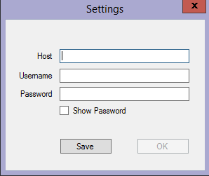
Hit the Test Connection button and make sure it works.

Edison Uploader
Edison Uploader

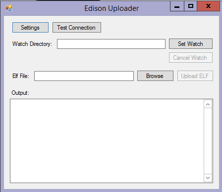
Next press Set Watch. This is going to watch a directory (recursively) for any new or modified .elf files. It defaults to the Arduino location: C:\Users\<USERNAME>\AppData\Local\Temp. If you are using Visual Micro in Visual Studio the location is C:\Users\<UserName>\AppData\Local\V.Micro\Arduino\Builds\.

If you are using different software, build the project with verbose mode enabled and determine where the elf file is being placed. Next build a complete new project and were where that file is placed. The path you want for the watch is the root path that is common between those two locations.

Once the watch is set every time the sketch is compiled a message window will pop up asking if you want to upload that sketch. Click Yes and it will fill in the path (you can also manually browse to an elf file). Press Upload ELF and it will upload that sketch to the Intel Edison.

Easy to setup and use: Compile->Yes->Upload ELF.

Release on Github

New Life for an Old Controller

An exciting part about getting into microcontrollers and circuits is finding new life for old pieces of hardware. All my old electronics end up in a plastic tub that collects and collects, but nothing ever happens to it. This tub has been collecting electronics for almost 15 years. Now I can start putting them to use. Good use…I don’t know, but at least use them for learning purposes.

One of the devices I had was a PC Pro Pad 4 that has a ton of buttons and switches, but connects with a Game Port, which is no longer used or made anymore. I decided that I could try a project where I hooked it up and used it as an input device for an Arduino. The final piece I needed was a connector for the game port, I thought I would have to find a sound card and cut off a game port from it. Digging through my electronics I found a PCI Game Port adapter, which worked perfect for connecting to a bread board.

Game Port PCI connector

I found several useful guides online for hooking up a joystick, so decided I could hook up the Pro Pad. The Pro Pad has 6 buttons, a direction pad, 4 switches for the button fire rate, one switch on the back (a/b), and two speed buttons. I was excited to find out how it used all these buttons considering the game port only has 4 digital pins and 4 analog pins. I assumed it had some crazy custom multiplexing of buttons or something of that nature and so I wired every pin up.

Here is everything setup, the guides I listed above have a great walk through.

Full wiring of Pro Pad 4

The yellow wires come from the analog joystick pins and are connected to ground with 100K resistors. The blue and white wires head to the Arduino analog ports.

Analog Wiring
Analog Wiring

The green wires are connected with 10K resistors to 5v from the button pins and then connected to the Arduino digital I/O headers.

Digital IO Wiring
Digital IO Wiring
Arduino wiring from bread board

With everything wired up I launched Ben Katz’s Arduino Program which outputs the values for the 4 analog and 4 digital ports. It worked great and I was immediately able to see how the A B C & D Buttons worked. The direction pad just the X and Y axis joystick controls and kept the value in the middle. A move up raised the analog Y high, down moved it low. Right raised the X high and left lowered it.

Not as complex as I hoped. It turns out there are only four buttons and the A/B switch on the back changes it from A B C D to A B L R. I couldn’t get the speed buttons to do anything nor the semi-auto/auto switches. I assume these do a quick high/low change for the button state and I will need to use interrupts.

Internals of the PC Pro Pad 4

With that I opened up the game pad and discovered it only used 8 wires of the 15. I mapped all the wires to their appropriate pins.

Game Port pins for Pro Pad 4

That’s when I decided to write up all my notes so I can optimize the connections.

My next step for this project:

  • Rewire the breadboard to just what I need
  • Write some new Arduino code to use interrupts and experiment with the Auto fire and speed buttons.
  • Hook it up to a Netduino (I think I need to do something with 5v vs 3.3v?)
  • Solder together my own shield
  • Design and print my own Arduino Shield

Update: Part 2 is here