Wireless Simon

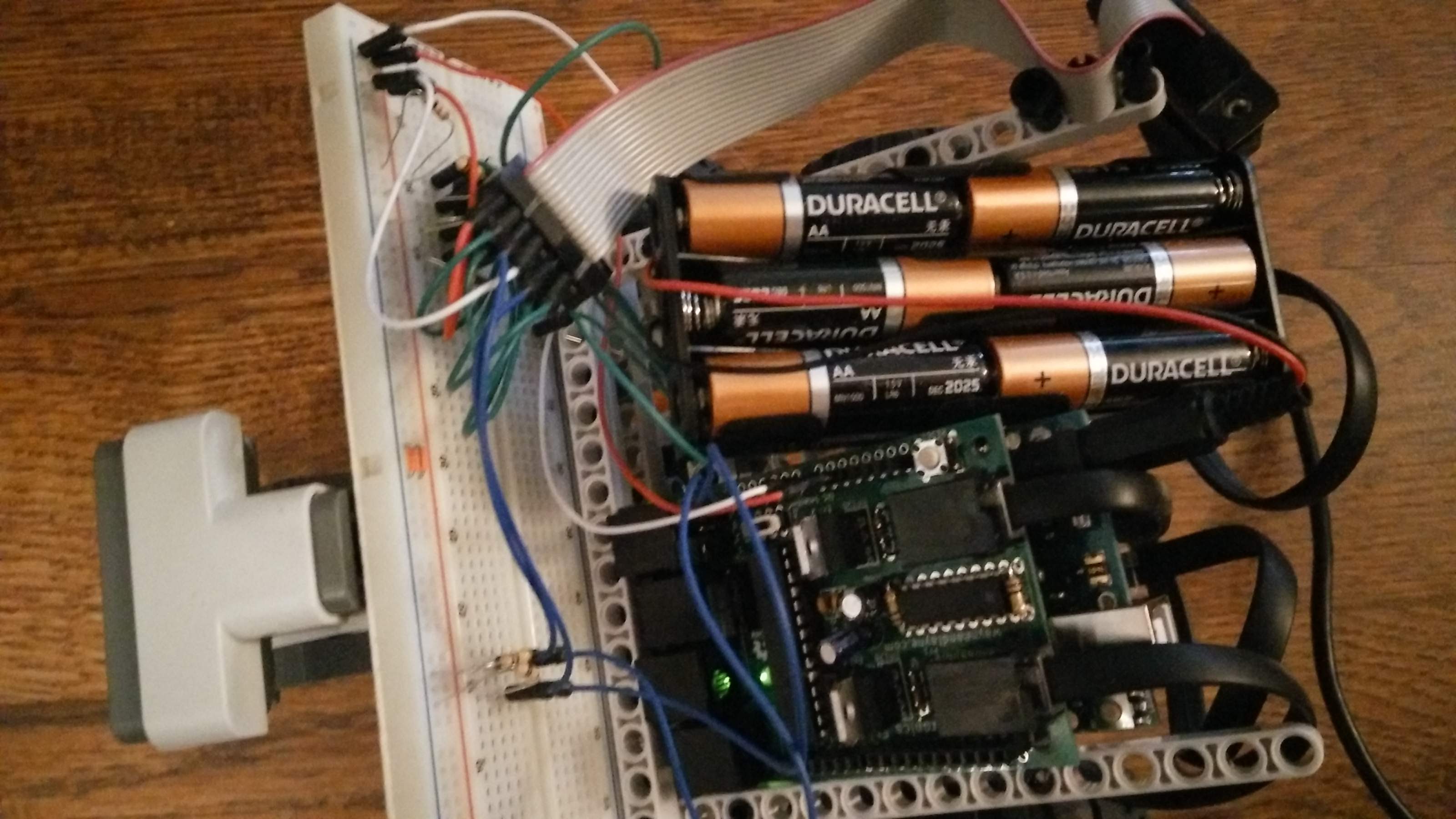
I really wanted to make Simon wireless. The breadboard and cord was a hassle and I didn’t want it to be permanent, so it constantly fell out. As a quick fix I tried using a Bluetooth Shield, however, the pin used to reset the Bluetooth was shared by one of the NXT motors. Depending on the position of the wheel the shield could either communicate or not.

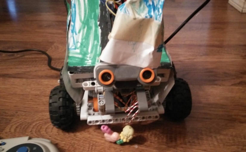
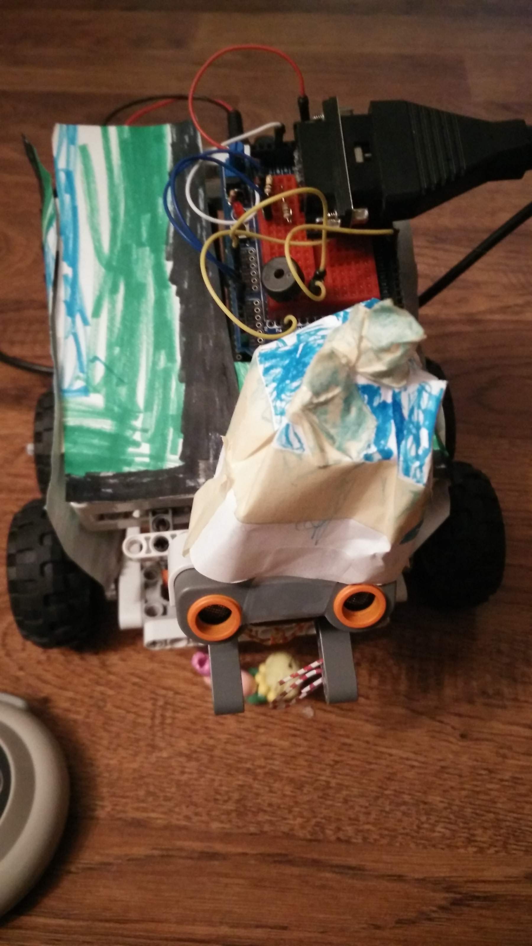
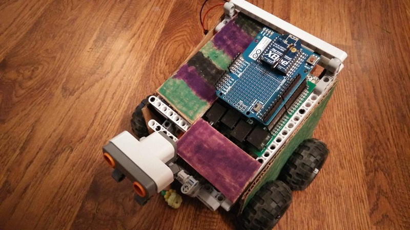
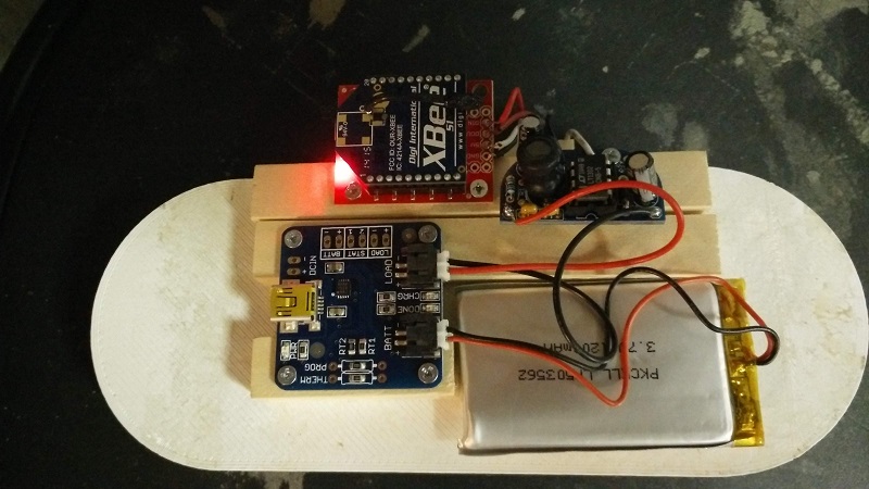
With the quick route unsuccessful, I decided to go ahead and build the wireless Esplora controller describe by Mike Barela on his blog. It look a lot of pieces but has worked great. I set it up with series 1 xBees which were surprisingly easy to get working. My daughter also upgraded his paneling to cardboard because the paper was too flimsy and coming off (he needs a new hat).

SimonSide

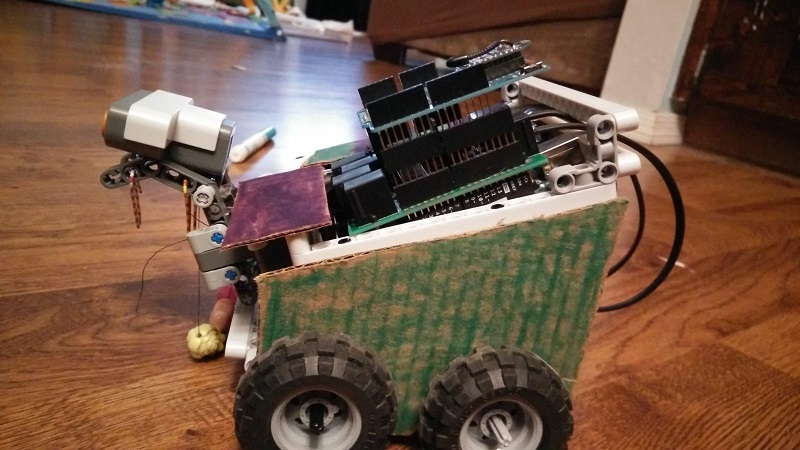
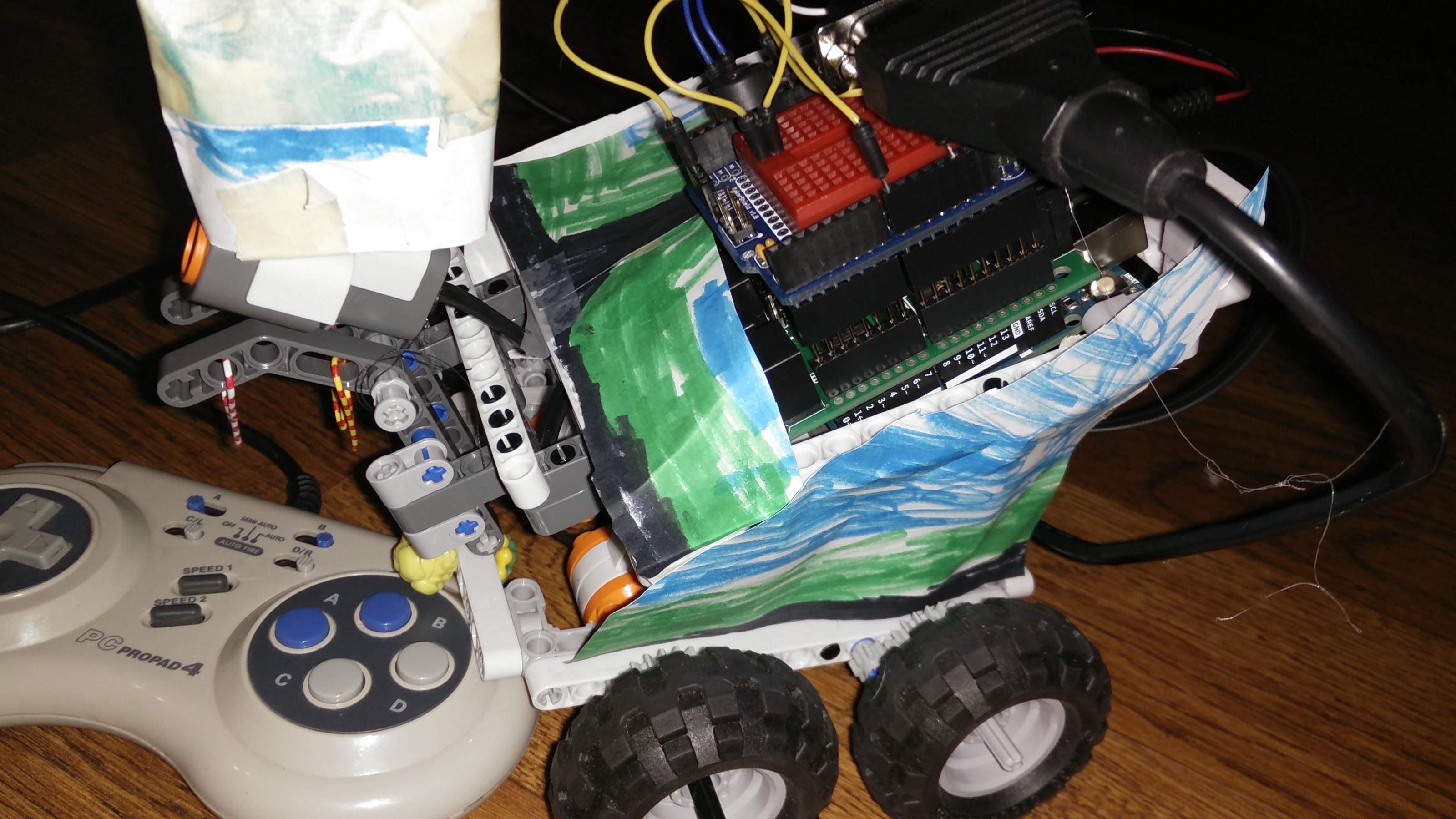
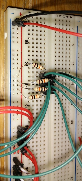
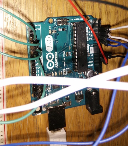
Simon now has the Uno, the NXT shield and wireless shield with an xBee on it. The breadboard and Gameport connection is gone. So is the buzzer for now.

ControllerTop

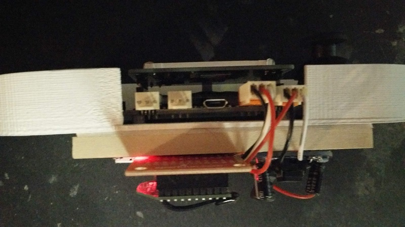
The only deviation from the Esplora Controller on the blog is how it is mounted. I had a partial 3D printed case for the Esplora so I mounted the Esplora inside of it. I then put some balsa wood on the back mounted with double sided mounting tape and screwed all the components to that.

ControllerBack

The programming part is simple. It just sends the character ‘u’, ‘d’, ‘l’, or ‘r’ depending on how the joystick is pressed and moves in that direction as well as displays it on the screen.

ControllerFront

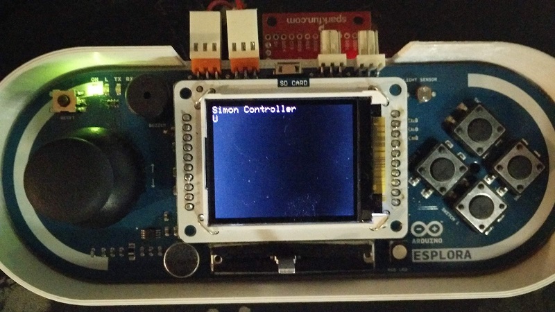
I have a lot planned for the controller now. Besides sending the joystick position there are 4 buttons (and the joystick button) that can be sent. I want to use the linear potentiometer to move a servo attached to the range sensor. There is also the mic which I think my daughter might like yelling at to make things happen.

With the TFT panel I want to be able to display all the sensors coming off of Simon. So the range sensor, color, mics, switches, whatever we put on her. I would also like to get some LEDs on Simon.

The Esplora is a fun product for learning, but fairly useless to for connecting things. Using it as a wireless controller with a TFT panel turns it into an extremely interesting product. It is a discontinued product, but you can still get the Arduino Esplora Board on Amazon.


Meet Simon

I have been spending a lot of time working with microcontrollers and circuits. One of my majors goals is to build an awesome, complex robot with my daughter. She has all kinds of ideas for how it should act (and so do I). We have been talking about it since watching Battle Bots, which was renewed for a second season! Here is our first prototype, Simon.

SimonR1

Simon is built with an Arduino Uno and the Lego Mindstorm NXT kit. Her chassis is based on this build. The Arduino connects to the NXT sensors and motors using a Bricktronics Shield. The first version had the GamePad connected through a breadboard and a button sensor on the front that prevented Simon from moving if she was touching something.

SimonTop

I attached a maker board to the top to wire in the Game Pad better. Only the X/Y analog controls are wired up. We also removed the button and connected the ultra sonic sensor instead. On the maker board we also put a buzzer. Now if something is too close to the front of Simon, Simon complains through the buzzer. My daughter like to bug and instead of driving Simon she prefers to get into Simon’s face and make her yell.

SimonSide

Finally, Simon also got dressed up. We placed panels on her, a hat, there are earrings (colored paperclips) and a necklace my daughter made.

The next step for Simon is to attach her to a wireless control using an Esplora.

If you want to meet Simon, we will be the Barnes & Noble Mini Maker Faire at Coronado, for the Sunday night Meet the Maker event.


PC ProPad 4 Arduino Code and Connections

This is a followup to my previous post about the PC ProPad 4. I finally got a chance to figure out the full functionality. I wired it up only using the active connections and created a simple sketch to get more specific output from the connections.  I tried to design it so it would work for any GamePort connection.

PC ProPad4 wiring
PC ProPad4 Wiring.
Blue is wired from the X & Y to the analog pins
Green is wired from the buttons to the digital pins
Red is 5v
White is ground

Next a wrote a much more complex sketch specifically for the PC ProPad 4. It allows me to configure interrupts, buttons, speeds, etc. I also wrote it with the intention of controlling a mouse. The Uno only has two interrupts and can’t connect as a mouse, so that part is untested. This sketch and the PC ProPad 4 should ideally be hooked up to a Leonardo or Due. This will allow you to use interrupts for all the buttons and connect it as a keyboard/mouse to the computer.

I will try it on the Netduino, which I believe supports interrupts on all the pins. It seems sending 3v should be fine, I just have to make sure I actually change it to the 3v line so keep the Netduino safe.

The first question I had what was the semi-auto, auto and speed buttons do? When a button is set to semi-auto then holding down the button will continue to fire the bottom (change from high to low). When the button is set to auto, it will fire the button constantly without it being pressed. Once I figured that out I remembered all the Doom 2 games I played with direct modem connections and setting my fire button to auto and having lots of fun.

The second question was what do the speed buttons do? I thought the speed button was some how associated with the analog direction pad, but this is not the case. The two speed settings set how fast the button is pressed when using auto and semi-auto settings. On Speed 1 the button is pressed about every ~30ms. On speed 2 it is pressed as fast as it can. The buttons need to be debounced and you can’t tell the difference between a bounce and the button firing automatically on speed 2, so it really just runs as fast as you are willing to debounce the button.

The next step is to see how this runs on the Netduino, then I’m going to try and create my own PCB board for a GamePort shield.

Easy Uploading to the Intel Edison

The most powerful feature of the Intel Edison is the wireless connectivity. Once the Intel Edison is setup, you can plug it into power and then easily connect to it to upload a new or updated program. This is especially nice for me since only one of my USB cords works with it.

The easiest way to use this feature is with JavaScript and pairing it with Gulp or Gist and Visual Studio. Unfortunately, I don’t know JavaScript at all, so any time I start looking at programming the Intel Edison I inevitably get lost in all the tutorials and projects surrounding Node.js and JavaScript.

I am comfortable in C and while at some point I want to be proficient in JavaScript, right now I want to play with my hardware toys and the JavaScript is just a distraction. The downside of C is that it became much harder to upload sketches and it is frustrating after getting use to how easy it was before. There are a couple of ways to make it automatic, but I decided to make a little program to make it automatic for me no matter what IDE or computer I am using.

So I sat down for a late night of hacking and the result was EdisonUploader and my first project on Github. Check it out.

The first time you launch it, you get a settings panel. Type in the name or IP of your Edison, as well as, the username and password, save it so it won’t ask again and click OK.

Settings Dialog
Settings Dialog

Hit the Test Connection button and make sure it works.

Edison Uploader
Edison Uploader

Next press Set Watch. This is going to watch a directory (recursively) for any new or modified .elf files. It defaults to the Arduino location: C:\Users\<USERNAME>\AppData\Local\Temp. If you are using Visual Micro in Visual Studio the location is C:\Users\<UserName>\AppData\Local\V.Micro\Arduino\Builds\.

If you are using different software, build the project with verbose mode enabled and determine where the elf file is being placed. Next build a complete new project and were where that file is placed. The path you want for the watch is the root path that is common between those two locations.

Once the watch is set every time the sketch is compiled a message window will pop up asking if you want to upload that sketch. Click Yes and it will fill in the path (you can also manually browse to an elf file). Press Upload ELF and it will upload that sketch to the Intel Edison.

Easy to setup and use: Compile->Yes->Upload ELF.

Release on Github

New Life for an Old Controller

An exciting part about getting into microcontrollers and circuits is finding new life for old pieces of hardware. All my old electronics end up in a plastic tub that collects and collects, but nothing ever happens to it. This tub has been collecting electronics for almost 15 years. Now I can start putting them to use. Good use…I don’t know, but at least use them for learning purposes.

One of the devices I had was a PC Pro Pad 4 that has a ton of buttons and switches, but connects with a Game Port, which is no longer used or made anymore. I decided that I could try a project where I hooked it up and used it as an input device for an Arduino. The final piece I needed was a connector for the game port, I thought I would have to find a sound card and cut off a game port from it. Digging through my electronics I found a PCI Game Port adapter, which worked perfect for connecting to a bread board.

Game Port PCI connector

I found several useful guides online for hooking up a joystick, so decided I could hook up the Pro Pad. The Pro Pad has 6 buttons, a direction pad, 4 switches for the button fire rate, one switch on the back (a/b), and two speed buttons. I was excited to find out how it used all these buttons considering the game port only has 4 digital pins and 4 analog pins. I assumed it had some crazy custom multiplexing of buttons or something of that nature and so I wired every pin up.

Here is everything setup, the guides I listed above have a great walk through.

Full wiring of Pro Pad 4

The yellow wires come from the analog joystick pins and are connected to ground with 100K resistors. The blue and white wires head to the Arduino analog ports.

Analog Wiring
Analog Wiring

The green wires are connected with 10K resistors to 5v from the button pins and then connected to the Arduino digital I/O headers.

Digital IO Wiring
Digital IO Wiring
Arduino wiring from bread board

With everything wired up I launched Ben Katz’s Arduino Program which outputs the values for the 4 analog and 4 digital ports. It worked great and I was immediately able to see how the A B C & D Buttons worked. The direction pad just the X and Y axis joystick controls and kept the value in the middle. A move up raised the analog Y high, down moved it low. Right raised the X high and left lowered it.

Not as complex as I hoped. It turns out there are only four buttons and the A/B switch on the back changes it from A B C D to A B L R. I couldn’t get the speed buttons to do anything nor the semi-auto/auto switches. I assume these do a quick high/low change for the button state and I will need to use interrupts.

Internals of the PC Pro Pad 4

With that I opened up the game pad and discovered it only used 8 wires of the 15. I mapped all the wires to their appropriate pins.

Game Port pins for Pro Pad 4

That’s when I decided to write up all my notes so I can optimize the connections.

My next step for this project:

  • Rewire the breadboard to just what I need
  • Write some new Arduino code to use interrupts and experiment with the Auto fire and speed buttons.
  • Hook it up to a Netduino (I think I need to do something with 5v vs 3.3v?)
  • Solder together my own shield
  • Design and print my own Arduino Shield

Update: Part 2 is here

Getting Started with the Intel Edison

Intel gave Quelab several Edisons and I was able to borrow one with an Arduino breakout board to play with. I was excited to give it a try and expected it to be as easy to setup as my Netduino, but it took quite a bit to get it going. I seemed to have some unique problems with my setup that took most of my time up that I will document below/

The first problem I ran into was getting power through the USB. The light would power on and the computer would do the USB plugged in chime. Then I would hear the USB unplugged chime and the lights would turn off. This would continue to loop forever. The Edison was not getting the power it needed through the USB, I expected this from my laptop. I hunted through all my power adapters and found a 12v 1500 ma power supply from an external hard drive that seemed to do the trick, no more rebooting and a solid light.

This is what the reboot loop looks like:

EdisonLoop

Unfortunately, I was then stuck trying to figure out why the Edison wasn’t being detected. No drive showed up in Windows and nothing was displayed in device manager. I tried different USB ports, restarted on a different computer, installed all the software and couldn’t get anything. I had actually given up and gone to bed when I decided the only thing I didn’t try was the USB cables. So I went through every micro USB cable I had in the house and on the 5th cable it mounted and worked fine! Only 1 of my 5 cables works. These aren’t bad cables, I can use them to connect cell phones to computers just fine. I still have no idea why they don’t work or why my cables have such problems and I haven’t found others with this issue, so I guess I just got all the Edison incompatible cables.

Finally, I went to get it on my network…my WEP protected network. This became another frustrating project. I ran through many guides and countless forum topics and could just never get it working. Why WEP? Well when my network was setup my family had several Nintendo DS systems that we used and those only works with WEP. Since then I forgot my password to my router and so it has stayed. I eventually bit the bullet and decided I would reset my router, it was past time to get off WEP anyways. As it turned out it took little time to reset my router, redo all my configuration, and reconnect all my devices. A fraction of the time I spent trying to get the Edison on WEP. The general solution to getting the Edison connected to a WEP network seems to be…don’t.

Now it is simple and amazing. There are so many ways to connect to it. I have used the Arduino IDE, Intel XDK IoT, and just copying over Node.js (I don’t know to program with any of these items right now btw). I think the Visual Studio hook up is most enticing and some great tutorials for getting everything setup are by Jeremy Foster.

With everything setup and on the network it is convenient to be able to just plug the power in and start writing programs for it from any computer. The only issue I have no is it doesn’t appear to always use the program I expect.

Sometimes it is running Node.js sometimes it is running an Arduino sketch and it isn’t always obvious to me why it chose that. I guess that is what happens switching between all the different possibilities.

CoderDojo ABQ

We had the first CoderDojo Abq event which was motivated by the Hour of Code event four months ago. It was incredible. The event occurred in the common area (The Core) of Quelab and it was packed.

coderdojo
Registration filled up and we had 18 youth attend to start learning Scratch. It was extremely exciting and positive. I spent many a nights worrying about whether it would be fun, if people might bored, find it too easy….or too hard; but in the end it went incredibly smooth. I think the kids, adults and volunteers all had a blast and the next CoderDojo Abq session (on the 25th) was sold out a 24 hours later.

The demand for this is amazing and I have heard nothing but excitement for the CoderDojo program. It was inspiring to watch all the kids have so much fun and then present what they made at the end. I expected one or two to have something they wanted to show and be willing to show it, but I think we ended up with seven kids presenting what they had made.

I hope this energy continues and am working on finding the people to expand it to more times so more youth will have the opportunity to join in.

Hacking Everything!

Chillhub
New Hackable Fridge @ Quelab

Quelab had an open house on Saturday called Hack All The Things. It was an amazing event and I ran a CoderDojo ABQ promotion were we got kids programming on Scratch and my Netduino. I should have gotten pictures and tweeted and done more promotion, but I was having too much fun. I did get one picture of the Hackable fridge Quelab won.

Intel provided Quelab with several Edisons for people to hack on. I was able to get to borrow one and hope to do some Internet Of Things projects and also write simply tutorials for Edison, similar to ones I used at the CoderDojo for the Netduino, which I will post online soon.

Finally, CoderDojo ABQ is happening April 11th and it will continue to occur at Quelab every 2nd and 4th Sunday from 10 – Noon. There has been amazing support from the people of Quelab and this should be a great event. Make sure to register at the website if you are interested.

Getting a Netduino 1 to work with VS 2013

Two of my favorite podcasters, Scott Hanselman and Saron Yitbarek, are putting on program this month called, March is for Makers. They normally focus on software, but for this month they are dedicating everything to hardware.

This reminded me of my Netduino 1, which I got for cheap and discovered the reason it was cheap is it was becoming obsolete. It only officially works with Visual Studio 2010, which I never bothered to install after upgrading to Windows 8 and so I haven’t used it for some time.

I thought I could get it working on newer software now that there had been more focus on .Net Micro Framework (progress seemed to have stalled) and the fact that the free community edition of Visual Studio 2013 was the full version and has full support for plugins. After piecing together information from different parts of the web I got it to work.
My initial setup:

Installation Steps:

The main trick that it took me a long time to figure out, was that you have to install both Netduino SDKs. The 4.2.2 has the drivers for the Netduino and the 4.3.1 allows it to work with Visual Studio 2013.

Creating a Project and Testing:

  • Plug in the Netduino and it will attempt to install the device.

Image
It should find the driver, if it doesn’t have it search for the driver at C:\Program Files (x86)\Secret Labs\Netduino SDK

  • Next open of MFDeploy, switch the Device to “USB” and the Netduino should be listed. You can ping the Netduino and and get its information by going to the Target menu and choosing Device Capabilities.

Image

  • Close MFDeploy and open Visual Studio 2013.
  • Create a New Project and choose the Netduino 1 Application

Image

  • Open the properties of your project and under the Application section change the Target framework to .Net Micro Framework 4.1 (or whatever version your Netduino is running).
  • Under the .Net Micro Framework section make sure the Transport is USB and the Device has your Netduino selected.

Image

  • Now you can write code and deploy it the NetDuino. If you need a quick sample to test run this:
using System;
using System.Threading;
using Microsoft.SPOT;
using Microsoft.SPOT.Hardware;
using SecretLabs.NETMF.Hardware;
using SecretLabs.NETMF.Hardware.Netduino;

namespace NetduinoApplication1
{
    public class Program
    {
        public static void Main()
        {
            OutputPort led = new OutputPort(Pins.ONBOARD_LED, false);
            while (true)
            {
                led.Write(true);
                Thread.Sleep(10000);
                led.Write(false);
                Thread.Sleep(10000);
            }
        }
    }
}

This just blinks the led on and off every second. Once it is deployed you should see the LED blinking.

Hopefully this will helps extend the life of the first generation of Netduinos.

Github Pages

I couldn’t believe how easy it was to get a page setup with Github. The other weekend I went to setup a Github repository for the upcoming CoderDojo ABQ and decided to use the Github Pages feature to get some information up and running.

I found a CoderDojo that was already on Github, whose format I liked. I forked it, renamed it and had a page up.

Next I downloaded the windows client, grabbed a copy of the repository and loaded up new imagery and put up some quick content. Committed it and I now you can see CoderDojoAbq. This took me about an hour and I still don’t really know Git at all, but I extremely impressed with how easy it was to get something nice setup. I was also impressed with the Windows client. I didn’t read any documentation and only knew the basics about how the Github pages functioned, everything was just natural and smooth.

My next plan is to get a tutorial up for how to fork and change the site and the push the changes to the official site (I’ll have to learn how to do this first).  Ideally, the students themselves will be able to update the website with their own projects or add features and designs.